Blinking LED’s on KL25Z Freedom Development Board
Lets begin our Embedded Development by Writing a simple code to blink multi color LED’s present on Freedom KL25Z Board. This tutorial will also help you to read Microcontroller Reference Manual which is an essential for writing any Embedded application.
*Note: Below steps are relevant to keil uVision IDE and might vary from IDE to IDE.
1.Create a new uVision project and give relevant name to it. It is better to give some generic name like “project” so that same project directory/folder can be copied to create another project.
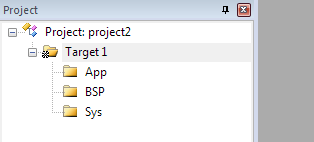
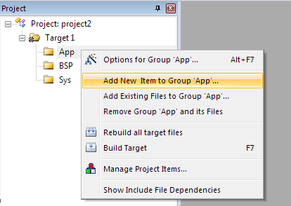
2. This time we will make our application modular so that it is easy to read for other person. Do this by adding multiple “groups” to your project as shown below (Right click on Target1 to add new group).

3. I usually create 3 different groups each having its own significance:
a. App: Application code
b. BSP: Board Support Package
c. Sys: System dependent code (e.g. C libraries, application stacks etc.)
You are free to choose any structure as per your like.
Similarly create these 3 different folders in your project directory to maintain your project files.

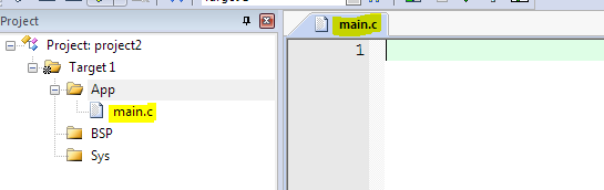
4. Create and add new file “main.c” to “App” group in your IDE and “App” folder in your project directory as shown below.

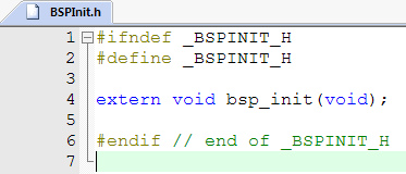
5. Similarly create and add new file “LEDBlink.c” to “App” group. Also create and add new files “BSPInit.c” and “BSPInit.h” to “BSP” group.

6. Define “main()” function in main.c file, which is a starting point to your code and call a function “bsp_init()” inside main.
Add definition of this function in “BSPInit.c” and prototype in “BSPInit.h”. For “main.c” to know definition of function “bsp_init()”, it is required to include “BSPInit.h” in main.c. This is called external linkage.


If you have observed carefully, compiler (actually Preprocessor) is not happy with code on line 1 of main.c.

This is because, when you include any file with double quotation e.g. “…”, preprocessor search for this file in your current directory, which in our case is “App”. However, the file “BSPInit.h” is not located inside “App” folder. It is actually inside “BSP” folder. So you should explicitly specify preprocessor about path of this file by updating file “Include Paths”.
To do that, go to menu option “Project -> Options for Target ‘Target1’…”. Select tab “C/C++” and click on small button besides “Include Paths” selection list.

New window will pop-up. Double click at the start of empty area of this window and you will see path selection button. Click on it to add Include paths. Browse to your local directory where these folders are located and add them to include paths. These are relative paths and remains same when you move your project to some other directory or some other machine.

Click OK to close this window and verify if paths are added in Include Paths selection.

Click OK to close this window. Now go to “main.c” file and you can see preprocessor is now happy.

7. Now try to compile your project be selection menu option “Project -> Build Target”. You will see your all source files are compiled properly but still you have 1 Error and 1 Warning and I guess you know why it is, if you have read previous tutorials. We have not yet defined “Interrupt Vector Table” and “Reset Handler” function.

8. Go to directory
“C:\Keil_v5\ARM\PACK\Keil\Kinetis_KLxx_DFP\1.15.0\Device\Source”
in your local drive and copy “system_MKL25Z4.H” and
“system_MKL25Z4.C” files from it and paste it into ‘BSP’ folder of your project directory.
Similarly, copy “startup_MKL25Z4.S” file from
“C:\Keil_v5\ARM\PACK\Keil\Kinetis_KLxx_DFP\1.15.0\Device\Source\ARM”
local directory and paste it into ‘BSP’ folder of your project directory.
Add both
“startup_MKL25Z4.S”and
“system_MKL25Z4.C” files to your project by right clicking on “BSP” Group and selecting option “Add Existing Files to Group ‘BSP’…”.


‘startup_MKL25Z4.s’ files gives definitions of Interrupt Vector Table and Reset_Handler function. ‘system_MKL25Z4.c’ gives definitions of SystemInit function. These files reduces your efforts to create Interrupt Vector Table manually.
You don’t have to add “mkl25z4.h” and “system_mkl25z4.h” files inside your project in uVision IDE unless you are expecting some modifications in them. Ideally, these files are provided by device manufacturers and they don’t need modifications.
9. Give one more try of compilation.

You are still getting 1 Error. This is because preprocessor can not find the definition of file “core_cm0plus.h”. This file is related to CMSIS (see-m-sis) which stands for “Cortex Microcontroller Software Interface Standard”, is a vendor-independent hardware abstraction layer for the Cortex®-M processor series and defines generic tool interfaces. This CMSIS libraries comes by default with Keil uVision IDE installation. These library files are included in “mkl25z4.h” header file and they are unknown to preprocessor yet. We need to include them in ‘Include Paths’.
The best way to do this is copy all CMSIS library files from your local directory
'C:\Keil_v5\ARM\PACK\ARM\CMSIS\5.4.0\CMSIS\Core\Include'
to your project directory. Create new folder ‘CMSIS’ inside ‘BSP’ folder of your project directory and paste these files here.

Now add this CMSIS folder to ‘Include Paths’ of IDE. This way all Include Paths are relative and not absolute with any dependency.

10. Now Rebuild your code and it will compile without any Error or Warning.

You are not Done yet. You still have not written any code to blink LED’s. But don’t worry, you are very close to it.
11. In order to blink LED’s on KL25Z Freedom, you should be aware of Freedom KL25Z board Hardware related to LED’s. In the reference manual of KL25Z, it is specified as below.


You can see, all LED’s are ‘Common Cathode’ and so they should be driven LOW (0v) to turn ON and driven HIGH (+3v) to turn OFF by Microcontroller’s digital output pin.
Red LED is connected to pin 18 of PORTB (PTB18), Green LED is connected to pin 19 of PORTB (PTB19) and Blue LED is connected to pin 1 of PORTD (PTD1).
12. From the above information, we can conclude that we need to configure PTB18, PTB19 and PTD1 pins in software as digital output pins. They should be default set to LOW so that LED’s are not turned ON by default. To do that you should first read KL25Z Reference Manual and particularly section on “General-Purpose Input/Output (GPIO)”.
You need 3 main things to configure GPIO’s:
- Configuring type of pin (GPIO/Analog/PWM etc.).
- Configuration Direction of pin.
- Writing Data on pin (HIGH/LOW).
Configuring type of Pin:
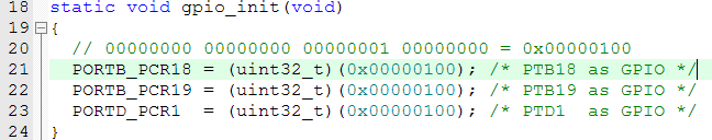
Go to the section “Port control and interrupts (PORT)” of KL25Z Reference Manual and go to definition of “Pin Control Register n (PORTx_PCRn)”. Bits 10 to 8 of this register are undefined at reset and needs to be configured as ‘001’ to configure pin as GPIO.

Go to uVision IDE and configure register PORTB_PCRn and PORTD_PCRn to configure PTB19, PTB19 and PTD1 pins as GPIO in “gpio_init()” function. The ‘Memory Map’ for PORTx_PCRn register is defined in “mkl25z4.h” header file.
Configuring Direction of pin:
Go to section “General-Purpose Input/Output (GPIO)” of KL25Z Reference Manual and see definition of “Port Data Direction Register (GPIOx_PDDR)”.

By default all pins of PORTx are configured as GPIO Input. We need to change them to output. So add below code in “gpio_init()” function.

Writing Data on Pin:
Go to section “General-Purpose Input/Output (GPIO)” of KL25Z Reference Manual and see definition of “Port Data Output Register (GPIOx_PDOR)”.

By default all pins are driven LOW. We need to set PTB18, PTB19 and PTD1 to drive HIGH due to common cathode LED configuration so that LED’s remains OFF after BSP Initialization.

13. Another very important thing to remember with KL25Z Microcontroller is, by default the clock to GPIO PORT circuitry and other peripherals of MCU is turned off to reduce power consumption of device. This is also applicable to other MCU’s. So before writing anything to GPIO PORT Registers or other peripherals, clock to GPIO PORTS or peripheral must be turned ON.
Refer section “System integration module (SIM)” from KL25Z Reference Manual and see the definition of “System Clock Gating Control Register 5 (SIM_SCGC5)”.


Update “gpio_init()” function to Enable clock to PORTB and PORTD.

So we are done with GPIO PORT initialization for LED controls. Now we will add code to blink LED’s. Add below code in “LEDBlink.c” file.
#include "mkl25z4.h"
#include <stdint.h>

static void delay(void);

#define red_LED_on()    {GPIOB_PDOR &= ~((uint32_t)(1 << 18));}
#define red_LED_off()   {GPIOB_PDOR |=  ((uint32_t)(1 << 18));}

#define green_LED_on()  {GPIOB_PDOR &= ~((uint32_t)(1 << 19));}
#define green_LED_off() {GPIOB_PDOR |=  ((uint32_t)(1 << 19));}

#define blue_LED_on()   {GPIOD_PDOR &= ~((uint32_t)(1 << 1));}
#define blue_LED_off()  {GPIOD_PDOR |=  ((uint32_t)(1 << 1));}

void control_LEDs(void)
{
	red_LED_on();
	delay();

	red_LED_off();
	blue_LED_on();
	delay();

	blue_LED_off();
	green_LED_on();
	delay();

	green_LED_off();
	delay();
}

static void delay(void)
{
	uint32_t i,j;
	for (i=0; i<2000; i++)
	{
		for (j=0; j<1000; j++);
	}
}
Also create new file “LEDBlink.h” and add below code into it.
#ifndef _LEDBLINK_H
#define _LEDBLINK_H

extern void control_LEDs(void);

#endif // end of _LEDBLINK_H
Finally update “main.c” to call “control_LED’s()” function.
#include "BSPInit.h"
#include "LEDBlink.h"
#include <stdint.h>

int main()
{
	// Initialize your Board Support Package
	bsp_init();

	for (;;)
	{
		// control/blink LED's
		control_LEDs();
	}
}
Now start the debug session and ‘run’ the code to see LED blinking. You will observe Red, Blue and Green LED’s blinks in a sequence with some delay in between them.
You can download entire code from here:
https://github.com/mahphalke/learningmicro/blob/master/Embedded%20Tutorials/LEDBlink.rar
Try experimenting with your code to understand it clearly. In the next tutorial we will explore the concept of Memory Mapped IO and use of volatile qualifier. We will also more explore on Debug windows and disassembly code.

Very well done. Thanks.
I noticed one (probably a) typo. It says, “You can see, all LED’s are ‘Common Cathode’ ….”. I think you meant Common Anode. Anodes are tied together and connected to the 3.3V source. So to turn on the LEDs you will need 0 V on the cathode. Just thought you may want to correct that.
Again, thank you.
LikeLiked by 1 person
How are you using delay function? How can you make it to 1 second delay?
LikeLike
Can you please add the tutorial for the self driving car? Like PID control dynamic steering control also dc motor acceleration and deceleration?
LikeLike
0 Pingbacks